My nephew (he’s four years old) often asks me “who decided that…” certain things are the way they are. Most of the time, I have no clue, so I respond “I don’t know. Go ask your dad.” But once in a while, I do know the answer and it has to do with some obscure bit of history.
For example, why is a men’s blazer called a blazer? How is it different from a men’s dress coat? If you have never noticed, a blazer is distinguished from a dress coat by the buttons or number of buttons (a blazer has more than a regular coat) on the sleeves. The reason is, in the 19th century, aboard the HMS Blazer (a British naval ship), the captain of the ship was so disgusted with his crew wiping their noses on the backs of the sleeves on their uniform coats, the captain had all of the crew sew many buttons on the sleeves, preventing the men from wiping their noses on the backs of the coat sleeve.
What in the world does this have to do with dispersion modeling? Many of the decisions made regarding modeling guidance that is in rule or user’s guides did not just materialize out of thin air. There is a rationale and back story of how some of these decisions were made. When it comes to how AERSURFACE should be used and applied, I just happen to be in the room when many of these discussion took place. Knowing the history helps explain why changes were made from the initial guidance to the guidance we have today. Some of the artifacts of old guidance still appear and are used by some state agencies and can cause confusion, particularly when the guidance is explained in a courtroom setting.
Brief History of AERMOD
Development of AERMOD started in 1991. If you were to look at the source code of AERMOD, many of the subroutines were written in 1991. It wasn’t until April of 2000 that AERMOD was proposed as a regulatory preferred model. AERMOD was later
Between April 2000 and November 2005, there were several regional, state, and local modelers meetings organized by EPA. I believe the most significant meeting of the regulatory modelers was in either May 2000 or May 2001. I can’t remember the exact date. The meeting was in Chicago, there was an energy crisis in California at the time, and it was a very cold spring in the mid-west, as the temperature in Chicago had not yet gotten to 50°F for the year by the first week of May. Regardless of which year it was, the meeting agenda was dominated by discussions on AERMOD.
At the time of the meeting, AERMOD was not a completely finished model. There were no algorithms for downwash and a few other features that were present, and relied upon, in the previous preferred model, ISCST3, which AERMOD was to replace. EPA modelers that developed the code (overworked and under-appreciated) had not been able to finish writing the code for the model system of programs by the rollout date.
Though there were many discussions of many issues, the most spirited and memorable, was the discussion regarding AERMET, the meteorological preprocessor for AERMOD. The presentation by EPA staff went over how AERMET was different from PCRAMMET, the meteorological processor for ISCST3. Rather than empirical values for the dispersion coefficients that were used in ISCST3, AERMOD, with the help of AERMET, calculated dispersion coefficients based on similarity and turbulence theory.
Key items needed to determine the dispersion coefficients were the meteorological surface characteristics albedo, Bowen ratio, and roughness length. These critical characteristics were to be coupled to the data being gathered. Using NWS observations was not going to be sufficient, unless the turbulence profiles were both laterally and vertically representative. The implication was that each site applying for an air quality permit would need to gather a full year of meteorological data before modeling could be commenced.
Now Texas, which reviews over 200 dispersion modeling analysis per year, with most of those analyses being in support of minor source NSR, had an “objection” to this implied requirement. When we asked what the criteria were to determine lateral and vertical representativeness and what the procedure would be to make that determination, there was no answer.
Though I am not 100 percent certain, the implied requirement for an onsite meteorological tower to gather data for AERMOD is where the guidance to apply AERSURFACE at the met tower location came from. At the time, it sounded like a requirement, but now it is a suggestion.
The Illusion of Precision
During the presentation on AERMET at the Chicago modelers meeting, the explanation given why the surface characteristics had to be at the location of the meteorological tower was
To put the data precision into perspective, let’s take a look at the precision of the data gathered at NWS stations. The wind direction is recorded to the nearest 10 degrees; not tenth, but 10. The wind speed is recorded to the nearest knot, which would mean each reading would have an inherent error of at least ±10%. In the early 2000’s, prior to AERMINUTE, the observations are 2 minute averages but represent the entire hour.
Regarding the precision of the model itself, remember AERMOD is a steady-state model, meaning the wind has the same speed and direction from the emission source to infinity, or at least across the entire modeling domain. Also, the exact same meteorology is applied over the entire modeling domain, which would be at least 400 km2 up to 10,000 km2 in size.
The reason for mentioning the precision of the data is to address the issues of mismatching surface characteristic values with meteorological data being gathered. Given all the inherent error in the data, it is unlikely that surface characteristics of the application site and the derived meteorological data would not be representative of the area near the application site.
Practical Conflicts with Suggested Guidance
A common conflict between the regulatory guidance and technical appropriateness occurs when the land cover near the NWS station is significantly different
In the figure below, the area around the NWS station is 70% urban and 30% rural based on recent land cover data.
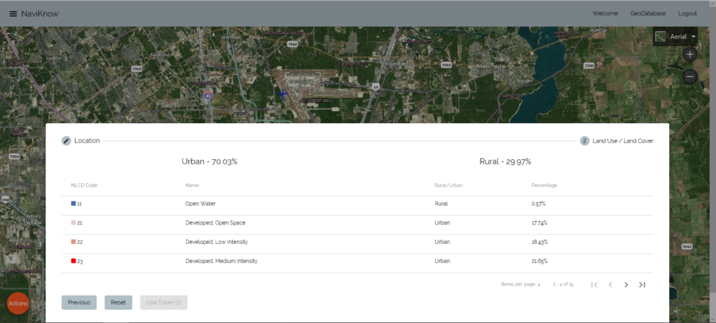
However, the land cover of a nearby industrial site is 33% urban and 67% rural. Though the analysis to calculate albedo, Bowen ratio, and roughness length would go into more detail, the differences in overall urban and rural makeup demonstrate that the calculated values would be significantly different between the two locations.
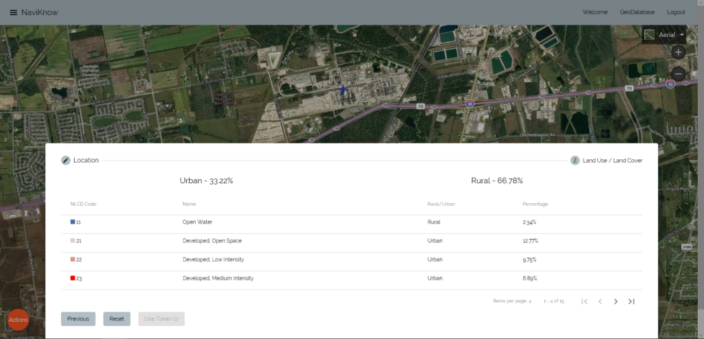
If in a courtroom setting, it is going to be difficult to explain that the land cover of the NWS station is representative of the application site.
If you decide to apply AERSURFACE at the application site, there is a nuanced issue that could raise a few questions. The guidance provided in the AERSURFACE User’s Guide and in the AERMOD Implementation Guide, highly suggests using a 1 km radius for the roughness length calculation. Though that guidance seems clear enough, there is no guidance on where the origin or center of this circular area should be placed. Many industrial sites can be quite large, to the extent that the surface characteristic values will differ depending upon where the center of the 1 km radius circle is located.
Below is a typical large industrial site. The site is about 6 km east to west and 2 km north to south. Notice that the site is surrounded by nonindustrial land cover.
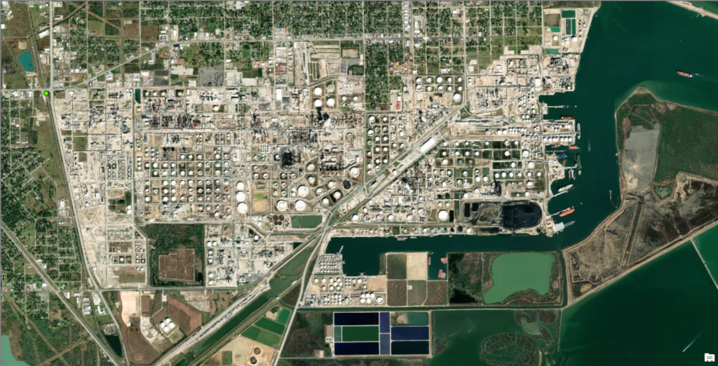
The initial thought is to position the origin of the surface characteristic analysis area at the centroid of the site, as shown below.
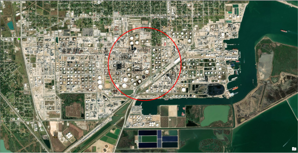
With a site so large, and even with sites not so large, the project triggering an air quality permit action is most likely not going to be the site centroid. If the project is to modify a set of boilers and heaters, is the center located at the centroid of the project area on the northwest portion of the site? This location would include residential land cover.
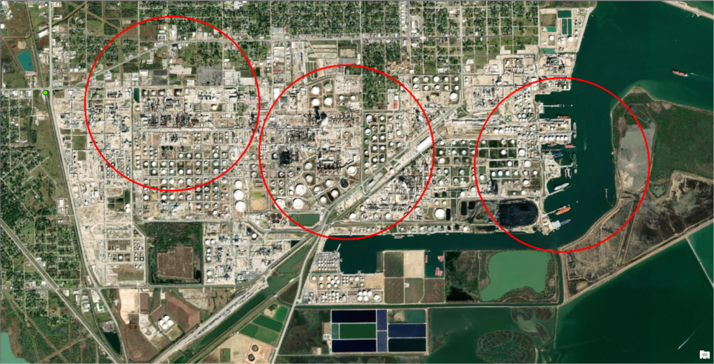
If the project is regarding barge and ship loading and associated storage tanks, is the center located at the centroid of that project area on the east side of the site. This location would include a large portion of open waters and marshlands which would significantly reduce the calculated value of the roughness length.
If this situation is not confusing enough, remember that, regardless of where you place the analysis area, the values that are calculated are applied to then entire modeling domain that can be as large as 10,000 km2.
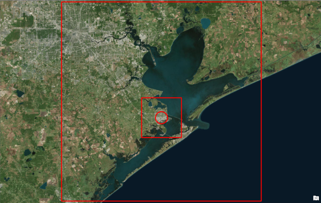
How are you going to explain and justify your selections?
How to Justify Your Selections and Follow the Guidance
Dispersion modeling involves a lot of details. If you don’t take a step back from all the potential choices that can be made, you can drive yourself insane. The most important item to remember is that dispersion modeling is NOT an exact science. Modeling is a means to make an estimate and a good one at that.
The one bit of guidance that should protect you from an onslaught of legal challenges is in 40 CFR 51 Appendix W (the GAQM) section 1.0 (d):
Consistency ensures that air quality control agencies and the general public have a common basis for estimating pollutant concentrations, assessing control strategies, and specifying emissions limits. Such consistency is not, however, promoted at the expense of model and database accuracy.
You don’t have control over the accuracy of the model. You do have some control over the accuracy and appropriateness of the raw data going into the model, but not much. However, consistency is your saving grace. If there is one thing I have learned from having been in the position of defending modeling analyses in court is, if you have followed a process that makes sense and have followed it consistently, you are credible. The details can be debated, but the consistency of following a process is what really matters.
Summarizing
There has been a lot of information to digest in this article. Our recommendation is to apply AERSURFACE at the application site centroid. It is not perfect but it is consistently imperfect and defendable. Always confer with the state agency and EPA region that are reviewing the analysis as they have the final say. We are just offering a suggestion based on our experience.
If you found this article informative, there is more helpful and actionable information for you. Go to http://learn.naviknow.com to see a list of past webinar mini-courses. Every Wednesday (Webinar Wednesday), NaviKnow is offering FREE webinar mini-courses on topics related to air quality dispersion modeling and air quality permitting. We also have articles air quality issues at http://naviknow.com/news. If you want to be on our email list, drop me a line at [email protected].
One of the goals of NaviKnow is to create an air quality professional community to share ideas and helpful hints like those covered in this article. So if you found this article helpful, please share with a colleague.
